Piping Isometric.
Details of Piping Isometric
Piping isometric is a representation of a single pipe line in a process plant with exact dimensions and Bill of Material (BOM).
piping isometrics allow the pipe to be drawn in a manner by which the length, width and depth are shown in a single view.
INDEX:-
- What is Piping Isometric.
- What is the types Of Drawing use in Piping Isometric (Input Required for Isometric Reading)?
- The main body of a piping Isometric drawing?
- What are the different sections of an piping isometric drawing?
- Advantages of using isometric drawings?
- Piping elements drawn in an isometric view Or Isometric Symbol?
- Checking point before using the Isometric Drawings?
- Calculations for Piping data like ID ,IM, Surface area from Isometric drawing?
1. What is Piping Isometric?
- An isometric drawing is a pictorial representation in which three sides of an object can be seen in one view.
- An explanation of how piping isometrics are created from plan and elevation views is explained.
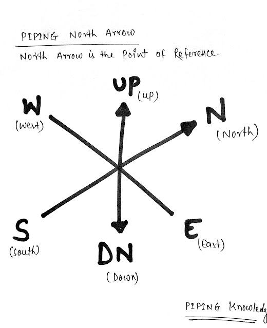
- The use of a North Arrow in establishing pipe orientation and routing on the isometric is shown graphically.
- The fitting, flange, and valve drawing symbols unique to isometrics are depicted.
- The use of coordinate and elevation callouts to determine configuration dimensions of the routed pipe is explained.
- The visualization, representation, and dimensioning of single, multi-angles, and rolling offsets are explained.
- Dimensional solutions of various pipe lengths using Pythagorean’s theorem and various trigonometric formulas are presented.
- Isometric piping drawings are used to define arrangements of pipework and fittings for fabrication and pricing purposes.
- An isometric drawing is a pictorial representation in which three sides of an object can be seen in one view.
- Isometric drawings are mostly used in the piping draw industry where a realistic view can be observed for laying out the pipes.
- It is mostly used as supplementary to plan ,GA, P&ID drawings
- The elevations and plan view drawings are used to prepare the isometric diagrams
- Isometrics provide a drafter that can calculate angular offset in pipe run.
- General Arrangement(GA)
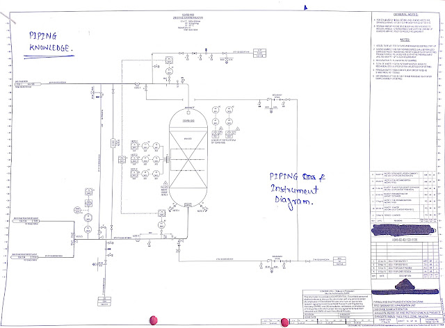
- P&ID Diagram (Piping and Instrumentation Diagram)
- Process Flow Diagram
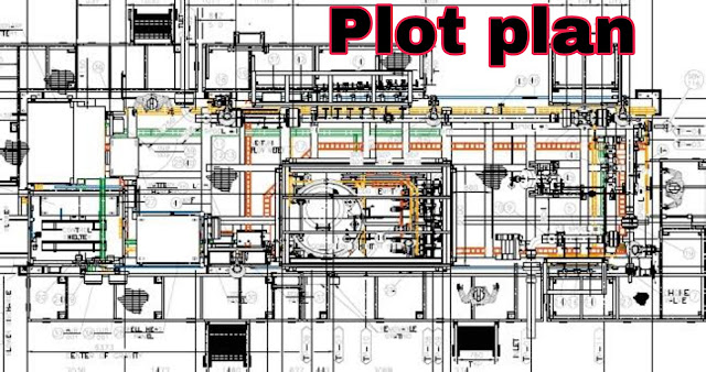
- Plot Plan Layout
- Orthographic and Isometric Drawings.
General Arrangement (GA) Drawing.
- The drawing includes overall dimensions, installation details, overall weight/mass, weights of sub systems, and service supply details.
- The General Arrangement Drawing includes references to the design documents.
- A GA Drawing stands for General Arrangement Drawing; it is used to communicate the important overall relationship between the main elements of the tank and key dimensions.
P&ID Diagram (Piping and Instrumentation Diagram).
- The P&ID is similar to the Process flow diagram but is more elaborate. It is a single line drawn schematic that will consist of major equipment, major valves, line sizes, controls and instruments.
- A piping and instrumentation diagram, or P&ID, shows the piping and related components of a physical process flow.
- It's most commonly used in the engineering field.
- P&ID is an abbreviation meaning 'Piping and Instrumentation Diagram'.
- Piping and Instrumentation Diagrams are graphical representations of a process system.
- These are fundamental to every standardized engineering project.
- These two-dimensional diagrams function as a blueprint for the engineering system's design.
3. Process Flow Diagram.
- A process flow diagram (PFD) is a diagram commonly used in chemical and process engineering to indicate the general flow of plant processes and equipment.
- The PFD displays the relationship between major equipment of a plant facility and does not show minor details such as piping details and designations.
4. Plot Plan Layout.
- The plot plan is basically an arrangement drawing that shows the equipment and supporting facilities (pipe racks, structures, buildings, roads) that are required for the process facility within a battery limit area, which will be designed for independent operation and shutdown.
- A site plan is produced in this step with the help of which the process engineer will place and arrange equipment.
- An orthographic drawing is a clear, detailed way to represent the image of an object.
- It may be used by engineers, designers, architects, and technical artists to help a manufacturer understand the specifics of a product that needs to be created.
- An orthographic drawing represents a three-dimensional object using several two-dimensional views of the object.
- It is also known as an orthographic projection.
- Line Number, Revision number, sheet number.
- Flow direction And Slop.
- Piping components Fitting and pipe details.
- Pipe Cut length details.
- Weld joint type size and its location.
- Continuation isometric number.
- Co-ordinates and Elevation of center of pipe
- Nozzle connection and Equipment number.
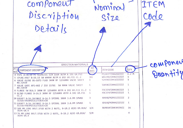
- Piping component or fittings item code and discreption.
- Material code or Item code.
- Nominal size of components.
- Quantity of components.
- Whether a field or shop item.
Bottom Section of Isometric Drawing.
 |
| Bottom section of Iso Drawings |
- Project name.
- Client.
- PMC ( Project management consultancy).
- Contractor details.
- Pipe line details i.e. Line number, Line size, fluid code, Design, and operating temperature, and Pressure Medium of HT.
- Piping class.
- Inch-Meter.
- Inch-Dia.
- Insulation type and Thickness .
- Painting type and codes of paint.
- NDT details.
- Steam tracing details
- PWHT details.
5. Advantages of using isometric drawings?
- The isometric also denote which piping lines need to be assembled and joined in the welding shop and which ones can be assembled directly on the field.
- The piping draw will provide easy understanding of the different planes through which the pipes move and Easy understand the line.
- This can also represent a line which not traveling in the exact North, south, east, west, up, or Down direction.
- This can indicate the type of joints to be done among piping components that will be used.
- This can give you fluid flow direction, Equipment connection details, and a special item attached to it in a single plain.
6.Piping elements drawn in an isometric view Or Isometric Symbol?
 |
| Some isometric symbol in Iso. |
.png) |
| ISO FITTINGS SYMBOLS |
 |
| Flange symbol |
 |
| Flange symbol |
 |
| Piping Fittings ISO symbol |
.jpg) |
| Miscellaneous symbol |
 |
| Iso valve Symbol |
7.Checking point before using the Isometric Drawings?
- Piping Isometric drawing dimensions are always from center to center of pipe.
- Pipe size is always written at any connecting point of Isometric.
- Co-ordinate and Elevation of Pipe is written at connecting points of Piping isometric drawing.
- Material description for Pipe is described in Piping isoemtric drawing on top right corner.
- Rolling in Isometric drawings are shown with Hatches.
- In case of Rolling of pipe, Its conventional direction not remains same to North, South, East or West.
- You must learn symbols of piping components and fittings to know required material for piping system.
- In top Left corner of Isometric considered direction is Indicated. Normally It is considered North.
- 1) Line Nos.
- 2) Line Specs
- 3) Start Point Location
- 4) End Point Location
- 5) Branch Connection
- 6) Valve Accessibility
- 7) Support
- 8) Insulation (For Insulated Line Only)
- 9) Instrument Connection
- 10) Flow Arrow
- 11) High Point Vent, Low Point Drain
- 12) Hydro Test Vent And Drain
- 13) Nozzle Connection
- 14) Nozzle Nos.
- 15) Equipment Nos.
- 16) Coordinates And Elevations
- 17) Iso North
- Bill Of Material
- 19) Valve Tag Nos.
- 20) Instruments Tag Nos.
- 21) Continuation Sheets or Iso. Nos.
- 22) Grid Location and Nos.
1) Pump Suction Is Bigger Than Discharge Line
2) Eccentric Reducer (Flat Side Top) Using For Pump Suction Line This Is Using For
Avoid The Air Block In Pump Suction.
3) Pump Suction Line And Compressor Suction Line Keep Always Downward Position,
No Loops Permitted To Pump Suction.
4) Psv Outlet Always Rising Position.
5) Check The Valve Accessibility For Maintenance Purpose. Valve Operating Height
Min 250mm To 1200mm From Floor Level.
6) Lift Check Valve Always Horizontally Using. Swing Check Valve Vertically and
Horizontally Using.
7) Control Station Operating Height 500mm to 750mm from Floor Level.
8) Shoe Not Required For Trunion. (Insulated Lines)
9) Headroom Clearance Minimum 2.2m from Ground/Floor Level.
10) Drip leg required for Steam Line Header.
11) Shoe Required For Insulated Lines (Steam, Chilled Water, Brine, and Steam
Condensate).
12) Shoe Not Required For Condensate Line When Line Will Be On Pipe Rack.
13) Nozzle Orientations Should Be Keeping As Per Piping Requirement.
14) Avoid The Obstacles. Keep A Piping Routing Neat And Clearly.
15) Control Stations Locates Side Of Near The Walls Or Columns
16) Give A Trunion Supports To Control Station Both Side Of Control Valves.
17) Use a Dike Wall Around The Equipments For Avoid The Liquid To Spread In The
Plant Area. The Volume Of Dike Wall Is 1.5 Times More Than Total Capacity Of
Equipments.
18) Use Weld neck Flange for Pressure Piping.
- Inch Meter can be estimated as Length of pipe (in meter) x Size of pipe ( in inch )
- Inch Dia is calculated as Size of Pipe joint ( in inch) x No, of Joints
- Pipe Weight is calculated as π x diameter of the pipe (in m) x length (in m) x thickness (in mm) x density of pipe material. Density of CS = 7.85 g/cm3
- The volume of Water required for hydro testing is estimated as π x {Pipe ID (in meter)}² x Length of Pipe
- Insulation Area (in m²) can be found as [π(Pipe OD+ insulation thickness)] (all in meter) x Length of Pipe (in meter)










Update soon
ReplyDeletePiping isometric drawings are essential in the field of engineering and construction. These drawings provide a detailed representation of a piping system in a three-dimensional view, showing the arrangement of pipes, fittings, valves, and other components. Isometric drawings help visualize the spatial layout of the piping system, including pipe lengths, angles, and connections. They aid in accurate fabrication, installation, and maintenance of piping systems, ensuring efficient and reliable operation. Piping isometric drawings are widely used in industries such as oil and gas, chemical, power generation, and manufacturing to ensure precise and effective design and implementation of piping networks.
ReplyDeleteFreture Techno