Basic Knowledge of Piping Isometric.
BASIC KNOWLEDGE OF PIPING ISOMETRIC
Isometric
Direction & location
Checking list of Isometric
Short Code of Isometric
Documents for isometric
Point remember for isometric checking
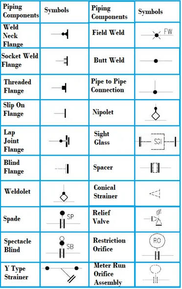
Basic Symbols for Isometric.
What is an Isometric Drawing?
- An isometric drawing is a type of pictorial drawing in which three sides of an object can be seen in one view.
- It’s popular within the process piping industry because it can be laid out and drawn with ease and portrays the object in a realistic view
- Isometrics are used as fabrication & shop drawings for pipe run fabrication.
- Isometrics also provide a drafter with the ability to calculate angular offsets in the pipe run.
- piping isometrics allow the pipe to be drawn in a manner by which the length, width and depth are shown in a single view. Isometrics are usually drawn from information found on a plan and elevation views.
- The symbols that represent fittings, Valves and flanges are modified to adapt to the isometric grid. Usually, piping isometrics are drawn on preprinted paper, with lines of equilateral triangles form of 60°.
- Isometric are not drawn to scale, dimensions are required to specify exact lengths of piping runs.
- Pipe lengths are determined through calculations using coordinates and elevations. Vertical lengths of pipe are calculated using elevations, while horizontal lengths are caculated using north-south and east-west coordinates.
- Piping isometrics are often used by designers prior to a stress analysis and are also used by draftsmen to produce shop fabrication spool drawings. Isometrics are the most important drawings for installation contractors during the field portion of the project.
Direction & location?
- Location and direction help to properly orient the isometric drawing A north arrow give direction and should ALWAYS point to the upper-right corner of the paper
- Structural reference points that provide location location can be shown on isometric
- Dimensions MUST always be given to points of reference; such as structures, existing equipment…etc
- Coordinates should also be shown on the isometric drawing.
Checking list of Isometric?
Short Code of Isometric ?
Documents for Isometric?
Point remember for isometric checking?
1. Pump Suction Is Bigger Than Discharge Line.
2. Eccentric Reducer (Flat Side Top) Using For Pump Suction Line This Is Using For Avoid The Air Block In Pump Suction.
3. Pump Suction Line And Compressor Suction Line Keep Always Downward Position, No Loops Permitted To Pump Suction.
4. Psv Outlet Always Rising Position.
5. Check The Valve Accessibility For Maintenance Purpose.Valve Operating Height Min 250mm To 1200mm From Floor Level.
6. Lift Check Valve Always Horizontally Using. Swing Check Valve Vertically and Horizontally Using.
7. Control Station Operating Height 500mm to 750mm from Floor Level.
8. Shoe Not Required For Trunion. (Insulated Lines).
9. Headroom Clearance Minimum 2.2m from Ground/Floor Level.
10. Drip leg required for Steam Line Header.
11. Shoe Required For Insulated Lines (Steam, Chilled Water, Brine, and Steam Condensate).
12. Shoe Not Required For Condensate Line When Line Will Be On Pipe Rack.
13. Nozzle Orientations Should Be Keeping As Per Piping Requirement.
14. Avoid The Obstacles. Keep A Piping Routing Neat And Clearly.
15. Control Stations Locates Side Of Near The Walls Or Columns.
16. Give A Trunion Supports To Control Station Both Side Of Control Valves.


.png)
.jpg)


Comments
Post a Comment